
Kennt ihr noch die Wii? Ich habe die Steuerung mit der Wii-Fernbedienung geliebt, gerade bei Mario Kart mit diesem Lenkrad. Als Kind fand ich das so faszinierend und wollte unbedingt ein ferngesteuertes Auto, dass ich mit diesem Lenkrad durch die Bude steuern kann. Also warum jetzt nicht selber bauen?

Zunächst bestellte ich erst einmal alle Materialen, da diese eine Weile brauchen würden bis sie ankommen.
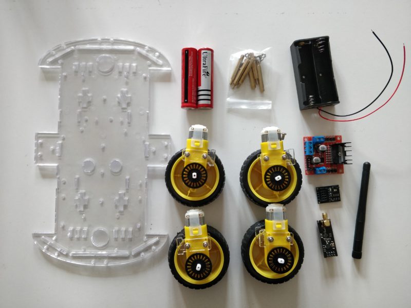
Für das Auto benötigte ich folgende Teile:
- DC Motor und Räder oder ein „robot car chassis“ Kit (wie auf dem Bild)
- einen Arduino
- L298N H-Bridge Motortreiber
- nRF24L01 Funkmodul mit Antenne
- nRF24L01 Adapter
- 2x 18650 Hochleistungsakkus mit 3,7V
- Ladegerät für die Akkus
- Hallterung für die Akkus
- Kabel zum Stecken
- breadboard
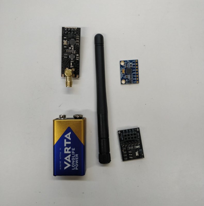
Und für die Steuerung:
- einen Arduino
- nRF24L01 Funkmodul mit Antenne
- nRF24L01 Adapter
- 9V Batterie und Adapter
- MPU 6050 Gyro mit Beschleunigungsmesser
- Kabel
- breadboard
Nach der Bestellung machte ich mich erst einmal an den Code. Es gibt sehr viele YouTube Videos zum Thema wie man ein ferngesteuertes Auto mit einem Handschuh steuern kann. Das Prinzip sollte sich doch leicht auf ein Lenkrad übertragen lassen. Doch die Codes waren sehr komplex und unverständlich. Nach etwas Recherche stieß ich auf etwas einfaches, was ich auch nachvollziehen konnte. Dieser Code arbeitet jedoch mit externen librarys von GitHub.
Librarys Links:
- RF24 — https://github.com/nRF24/RF24
- I2Cdev — https://github.com/jrowberg/i2cdevlib/tree/master/Arduino/I2Cdev
- MPU6050 — https://github.com/jrowberg/i2cdevlib/tree/master/Arduino/MPU6050
Nicht jeder Ordner hat einen grünen Downloadbutton. Ihr müsst zum übergeordneten Ordner und diesen downloaden. Dann könnt ihr im runtergeladenen Ordner wieder zur gewünschten Datei navigieren.
Der Code für den Arduino des Autos:
//Add the necessary libraries
#include <SPI.h> //SPI library for communicate with the nRF24L01+
#include "RF24.h" //The main library of the nRF24L01+
//Define enable pins of the Motors
const int enbA = 3;
const int enbB = 5;
//Define control pins of the Motors
//If the motors rotate in the opposite direction, you can change the positions of the following pin numbers
const int IN1 = 2; //Right Motor (-)
const int IN2 = 4; //Right Motor (+)
const int IN3 = 7; //Left Motor (+)
const int IN4 = 6; //Right Motor (-)
//Define variable for the motors speeds
//I have defined a variable for each of the two motors
//This way you can synchronize the rotation speed difference between the two motors
int RightSpd = 130;
int LeftSpd = 150;
//Define packet for the direction (X axis and Y axis)
int data[2];
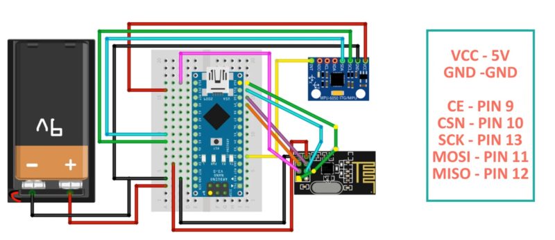
//Define object from RF24 library - 9 and 10 are a digital pin numbers to which signals CE and CSN are connected
RF24 radio(9,10);
//Create a pipe addresses for the communicate
const uint64_t pipey = 0xE8E8F0F0E1LL;
void setup(){
//Define the motor pins as OUTPUT
pinMode(enbA, OUTPUT);
pinMode(enbB, OUTPUT);
pinMode(IN1, OUTPUT);
pinMode(IN2, OUTPUT);
pinMode(IN3, OUTPUT);
pinMode(IN4, OUTPUT);
Serial.begin(9600);
radio.begin(); //Start the nRF24 communicate
radio.openReadingPipe(1, pipey); //Sets the address of the transmitter to which the program will receive data.
radio.startListening();
}
void loop(){
if (radio.available()){
radio.read(data, sizeof(data));
if(data[0] > 380){
//forward
analogWrite(enbA, RightSpd);
analogWrite(enbB, LeftSpd);
digitalWrite(IN1, HIGH);
digitalWrite(IN2, LOW);
digitalWrite(IN3, HIGH);
digitalWrite(IN4, LOW);
}
if(data[0] < 310){
//backward
analogWrite(enbA, RightSpd);
analogWrite(enbB, LeftSpd);
digitalWrite(IN1, LOW);
digitalWrite(IN2, HIGH);
digitalWrite(IN3, LOW);
digitalWrite(IN4, HIGH);
}
if(data[1] > 180){
//left
analogWrite(enbA, RightSpd);
analogWrite(enbB, LeftSpd);
digitalWrite(IN1, HIGH);
digitalWrite(IN2, LOW);
digitalWrite(IN3, LOW);
digitalWrite(IN4, HIGH);
}
if(data[1] < 110){
//right
analogWrite(enbA, RightSpd);
analogWrite(enbB, LeftSpd);
digitalWrite(IN1, LOW);
digitalWrite(IN2, HIGH);
digitalWrite(IN3, HIGH);
digitalWrite(IN4, LOW);
}
if(data[0] > 330 && data[0] < 360 && data[1] > 130 && data[1] < 160){
//stop car
analogWrite(enbA, 0);
analogWrite(enbB, 0);
}
}
}
Der Code für den Arduino des Lenkrades:
//Add the necessary libraries
#include <SPI.h> //SPI library for communicate with the nRF24L01+
#include "RF24.h" //The main library of the nRF24L01+
#include "Wire.h" //For communicate
#include "I2Cdev.h" //For communicate with MPU6050
#include "MPU6050.h" //The main library of the MPU6050

//Define the object to access and cotrol the Gyro and Accelerometer (We don't use the Gyro data)
MPU6050 mpu;
int16_t ax, ay, az;
int16_t gx, gy, gz;

//Define packet for the direction (X axis and Y axis)
int data[2];

//Define object from RF24 library - 9 and 10 are a digital pin numbers to which signals CE and CSN are connected.
RF24 radio(9,10);

//Create a pipe addresses for the communicate
const uint64_t pipey = 0xE8E8F0F0E1LL;

void setup(void){
Serial.begin(9600);
Wire.begin();
mpu.initialize(); //Initialize the MPU object
radio.begin(); //Start the nRF24 communicate
radio.openWritingPipe(pipey); //Sets the address of the receiver to which the program will send data.
}

void loop(void){

//With this function, the acceleration and gyro values of the axes are taken.
//If you want to control the car axis differently, you can change the axis name in the map command.
mpu.getMotion6(&ax, &ay, &az, &gx, &gy, &gz);

//In two-way control, the X axis (data [0]) of the MPU6050 allows the robot to move forward and backward.
//Y axis (data [0]) allows the robot to right and left turn.
data[0] = map(ax, -17000, 17000, 300, 400 ); //Send X axis data
data[1] = map(ay, -17000, 17000, 100, 200); //Send Y axis data
radio.write(data, sizeof(data));
}
Die Librarys einfügen: Sketch -> Bibliothek einbinden -> ZIP-Bibliothek hinzufügen
(Am besten ihr macht aus dem Ordner, den ihr auswählen wollt vorher eine zip-Datei.)
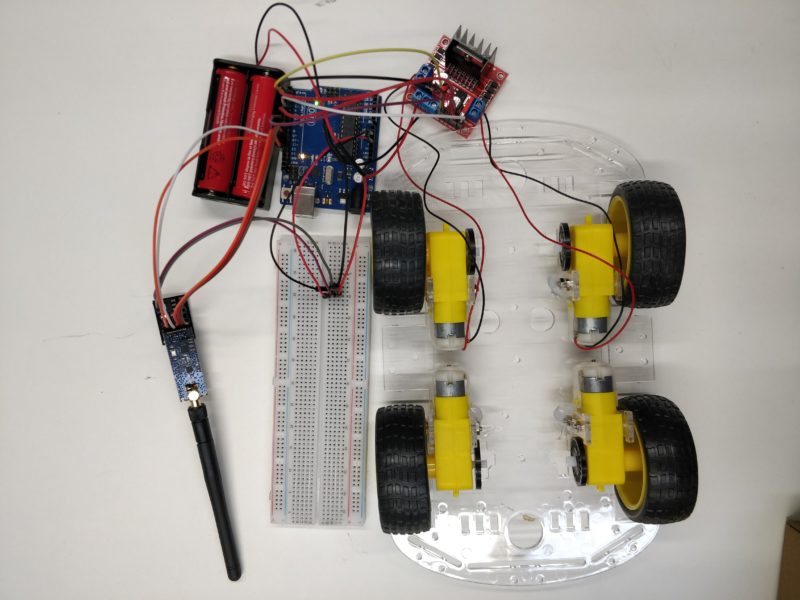
Um den Code nun testen zu können, musste ich warten bis alle Teile geliefert wurden und ich sie in der Hochschule zusammenbauen konnte.
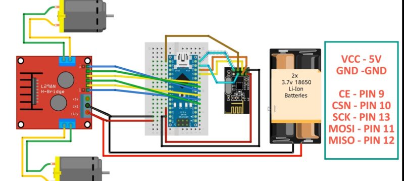
Bauplan Auto:
Bauplan Steuerung:
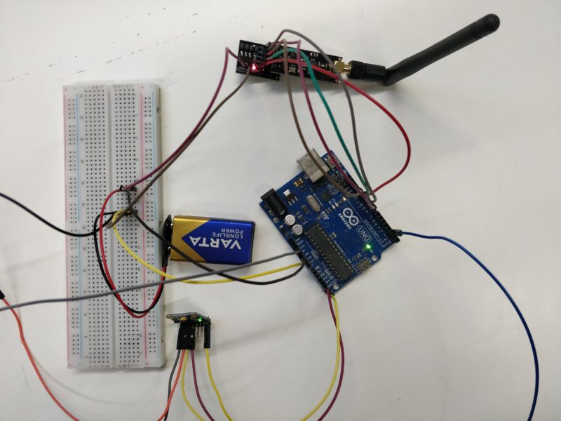
Nun ist alles bereit zum Testen. Der Code zeigt keine Fehlermeldung mehr und alles ist verkabelt, aber mein Auto fährt nicht. Das Signal kommt nicht beim Auto an. Die Senderantenne wollte einfach nicht senden.
Also spontaner Umstieg auf Esp’s, da diese direkt miteinander kommunizieren können.
ESP Variante:
Erst einmal alles neu verkabeln:
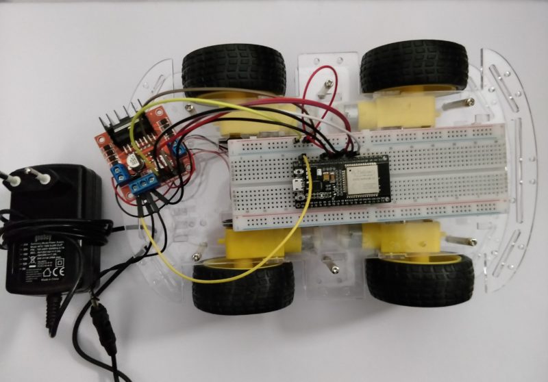
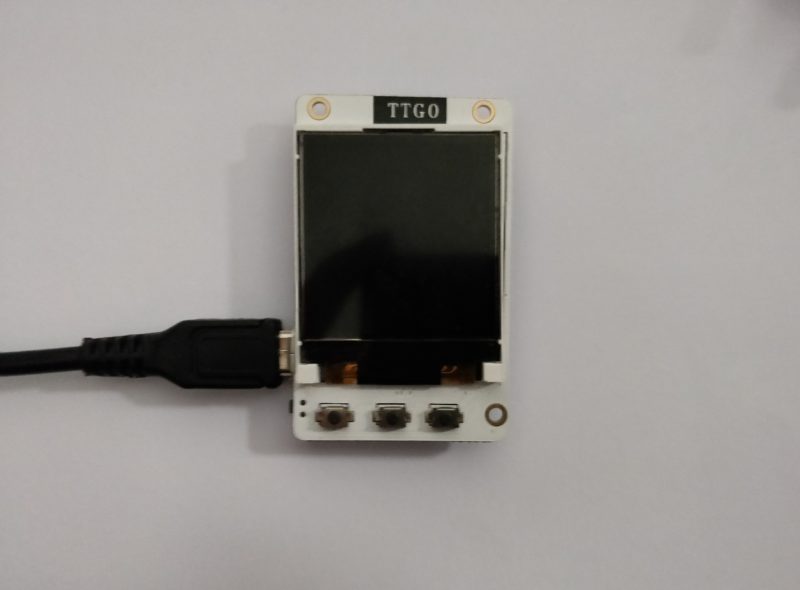
Für die Steuerung bin ich jetzt auf einen Esp TTGO umgestiegen, da dieser bereits den Lagesensor integriert hat.
Code Steuerung:
Hier muss noch die Bibliothek MPU9250 von asukiaaa eingefügt werden.
#include <MPU9250_asukiaaa.h>

#ifdef _ESP32_HAL_I2C_H_
#define SDA_PIN 19
#define SCL_PIN 18
#endif

MPU9250_asukiaaa mySensor;

#include <esp_now.h>
#include <WiFi.h>

// REPLACE WITH YOUR RECEIVER MAC Address
uint8_t broadcastAddress[] = {0xFF, 0xFF, 0xFF, 0xFF, 0xFF, 0xFF};

// Structure example to send data
// Must match the receiver structure
typedef struct struct_message {

int ax;
int ay;

} struct_message;

//Define packet for the direction (X axis and Y axis)
int data[2];

// Create a struct_message called myData
struct_message Data;

// callback when data is sent
void OnDataSent(const uint8_t *mac_addr, esp_now_send_status_t status) {
Serial.print("\r\nLast Packet Send Status:\t");
Serial.println(status == ESP_NOW_SEND_SUCCESS ? "Delivery Success" : "Delivery Fail");
}

void setup() {
// Init Serial Monitor
Serial.begin(115200);

// Set device as a Wi-Fi Station
WiFi.mode(WIFI_STA);

// Init ESP-NOW
if (esp_now_init() != ESP_OK) {
Serial.println("Error initializing ESP-NOW");
return;
}

// Once ESPNow is successfully Init, we will register for Send CB to
// get the status of Trasnmitted packet
esp_now_register_send_cb(OnDataSent);

// Register peer
esp_now_peer_info_t peerInfo;
memcpy(peerInfo.peer_addr, broadcastAddress, 6);
peerInfo.channel = 0;
peerInfo.encrypt = false;

// Add peer
if (esp_now_add_peer(&peerInfo) != ESP_OK){
Serial.println("Failed to add peer");
return;
}

#ifdef _ESP32_HAL_I2C_H_
// for esp32
Wire.begin(19, 18); //sda, scl
#else
Wire.begin();
#endif

mySensor.setWire(&Wire);

mySensor.beginAccel();
mySensor.beginMag();
}

void loop() {

if(mySensor.magX() > -17 && mySensor.magX() < 30 && mySensor.magY() > 35 && mySensor.magY() < 70){
datasend(0, 0);
delay(1000);
}

if(mySensor.magX() < -17 ){
datasend(1, 1);
delay(1000);
}

if(mySensor.magY() < 30 ){
datasend(1, 0);
delay(1000);
}

if(mySensor.magY() > 80 ){
datasend(0, 1);
delay(1000);
}

if(mySensor.magX() > 30 ){
datasend(-1, -1);
delay(1000);
}

mySensor.magUpdate();
Serial.println("print mag values");
Serial.println("magX: " + String(mySensor.magX()));
Serial.println("maxY: " + String(mySensor.magY()));
Serial.println("magZ: " + String(mySensor.magZ()));
Serial.println("horizontal direction: " + String(mySensor.magHorizDirection()));

Serial.println("at " + String(millis()) + "ms");
delay(50);

}
Code Auto:
</pre>
#include <esp_now.h>
#include <WiFi.h>//Add the necessary libraries
#include "printf.h"
// Motor A
int motor1Pin1 = 27;
int motor1Pin2 = 26;
int enable1Pin = 14;
// Motor B
int motor1Pin3 = 33;
int motor1Pin4 = 32;
int enable2Pin = 35;
// Setting PWM properties
const int freq = 30000;
const int pwmChannel = 0;
const int pwmChannel2 = 1;
const int resolution = 8;
int dutyCycle = 200;
//Define packet for the direction (X axis and Y axis)
int data[2];
// Structure example to receive data
// Must match the sender structure
typedef struct struct_message {
int ax;
int ay;
} struct_message;
// Create a struct_message called myData
struct_message Data;
// callback function that will be executed when data is received
void OnDataRecv(const uint8_t * mac, const uint8_t *incomingData, int len) {
memcpy(&Data, incomingData, sizeof(Data));
Serial.print("Bytes received: ");
Serial.println(len);
Serial.print("Char: ");
Serial.println(Data.ax);
Serial.print("Int: ");
Serial.println(Data.ay);
Serial.print("Int: ");
if(Data.ax == 1){
digitalWrite(motor1Pin1, LOW);
digitalWrite(motor1Pin2, HIGH);
}
if(Data.ax == 0){
digitalWrite(motor1Pin1, LOW);
digitalWrite(motor1Pin2, LOW);
}
if(Data.ax == -1){
digitalWrite(motor1Pin1, HIGH);
digitalWrite(motor1Pin2, LOW);
}
if(Data.ay == 1){
digitalWrite(motor1Pin3, LOW);
digitalWrite(motor1Pin4, HIGH);
}
if(Data.ay == 0){
digitalWrite(motor1Pin3, LOW);
digitalWrite(motor1Pin4, LOW);
}
if(Data.ay == -1){
digitalWrite(motor1Pin3, HIGH);
digitalWrite(motor1Pin4, LOW);
}
}
void setup() {
// sets the pins as outputs:
pinMode(motor1Pin1, OUTPUT);
pinMode(motor1Pin2, OUTPUT);
pinMode(enable1Pin, OUTPUT);
// sets the pins as outputs:
pinMode(motor1Pin3, OUTPUT);
pinMode(motor1Pin4, OUTPUT);
pinMode(enable2Pin, OUTPUT);
// configure LED PWM functionalitites
ledcSetup(pwmChannel, freq, resolution);
ledcSetup(pwmChannel2, freq, resolution);
// attach the channel to the GPIO to be controlled
ledcAttachPin(enable1Pin, pwmChannel);
ledcAttachPin(enable2Pin, pwmChannel2);
// Initialize Serial Monitor
Serial.begin(115200);
// Set device as a Wi-Fi Station
WiFi.mode(WIFI_STA);
// Init ESP-NOW
if (esp_now_init() != ESP_OK) {
Serial.println("Error initializing ESP-NOW");
return;
}
// Once ESPNow is successfully Init, we will register for recv CB to
// get recv packer info
esp_now_register_recv_cb(OnDataRecv);
}
void loop() {
ledcWrite(pwmChannel, dutyCycle);
ledcWrite(pwmChannel2, dutyCycle);
<pre>}
Nun bewegt sich alles wie gewünscht 😀 Nur benötige ich für das Auto noch einen stärkeren transportablen Akku, welcher auch nicht zu schwer für das Auto ist. Aber die Reichweite des Senders ist der Hammer *-*
(nicht über das Wasserzeichen wundern, musste das Video komprimieren für die Website)